Hardware
Overview
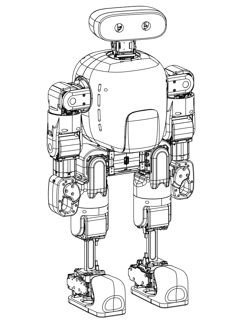
Mini Pi+ is a 27-DOF full humanoid robot platform evolved from Mini Pi.
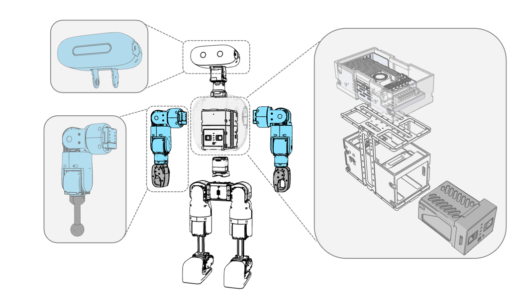
The system follows a modular design:
- Leg modules are fully reused from Mini Pi
- Upper body (waist, arms, head) is added via quick-release interfaces
- No modification to leg control strategy or driver layer is required
This design enables rapid iteration and extensibility.
Mechanical Structure
The robot consists of:
- Legs (fully reused)
- Waist (1 DOF)
- Arms (6 DOF × 2)
- Head (2 DOF)
Key properties:
- Height: ~75 cm
- Mass: ~13.84 kg
The modular structure enables rapid hardware extension without redesigning the core system.
Actuation System
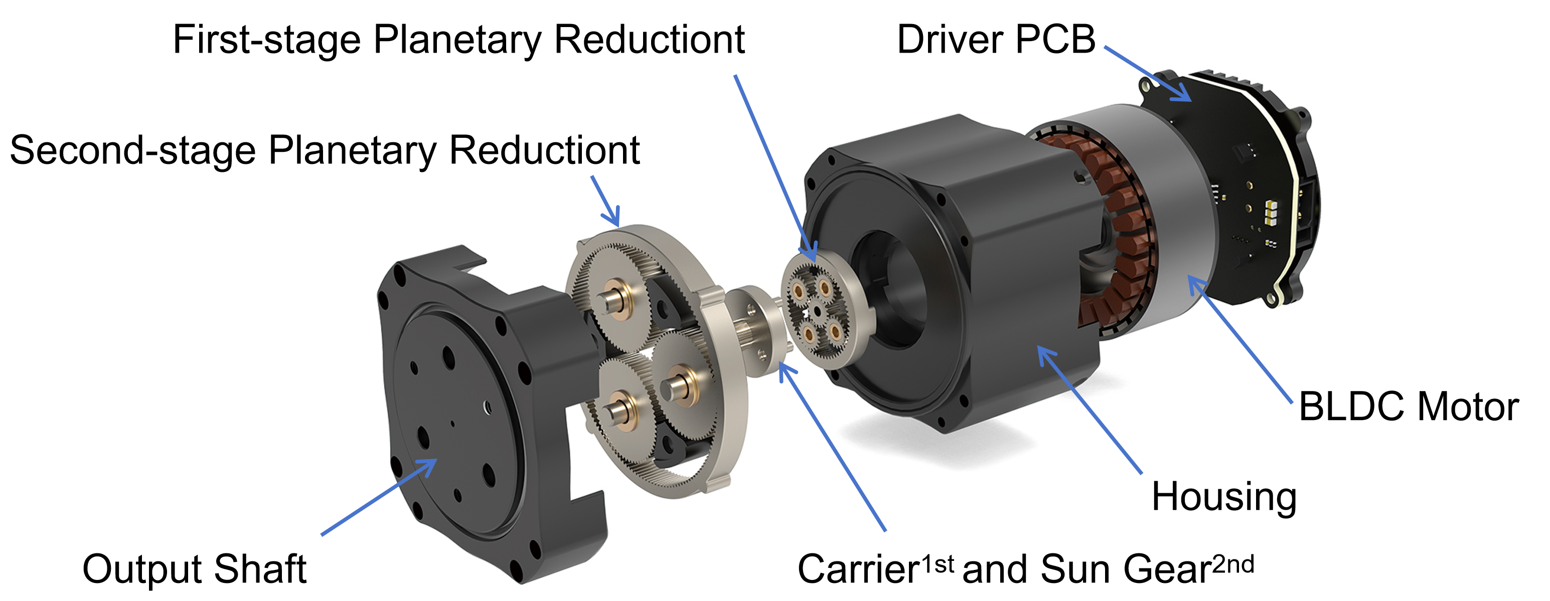
The platform uses integrated joint modules:
- HTDW-5036 (legs)
- HTCP-5031 (waist)
- HTDW-4438 (arms)
- HTDW-3536 (arms/head)
Key features:
- Integrated motor, gearbox, driver, and dual encoders
- Two-stage planetary reduction
- CAN FD communication (up to 1 kHz control loop)
Typical performance:
- Leg module peak torque: 21 N·m
- Arm module peak torque: 10 N·m
- Head module peak torque: 3 N·m
System Architecture
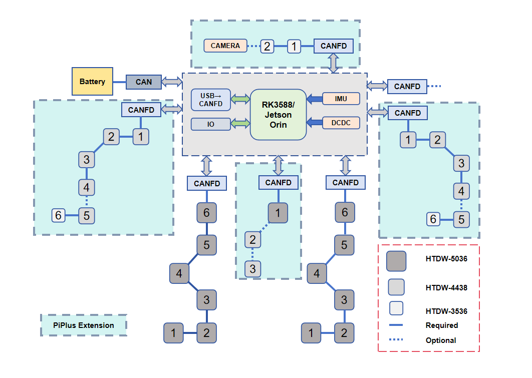
The system adopts a distributed control architecture:
- Central controller (RK3588 / Jetson platform)
- Multi-channel CAN FD communication
- Independent bus per subsystem
Each subsystem (legs, arms, waist, head) is connected via isolated CAN FD channels.
Main Control Unit
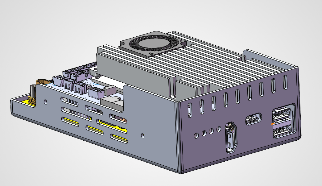
The main control unit integrates:
- RK3588 computing platform
- IMU
- Power management
- Communication interfaces
Specifications:
- 16 GB RAM + 128 GB storage
- Supports motion control, perception, and planning
- WiFi / Ethernet connectivity
- OTA update support
Control Panel
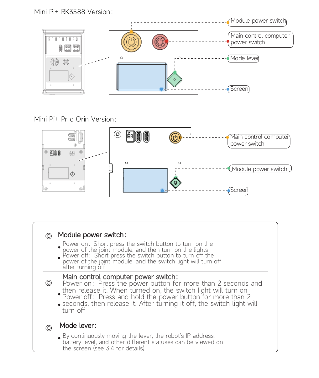
The robot provides a physical control panel for system operation and status monitoring.
Components
-
Module Power Switch Controls power to joint modules
-
Main Control Computer Power Switch Controls the onboard computing system
-
Mode Lever Used to switch display information (e.g., IP address, system status)
-
Screen Displays system information and status
Power Operation
Module Power
- Power on: short press → modules powered
- Power off: short press → modules powered down
Main Control Computer
- Power on: press > 2 seconds
- Power off: press > 2 seconds
Status Indication
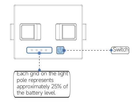
- The LED bar indicates battery level
- Each segment represents approximately 25% capacity
Notes
- Always power on the main control system before sending commands
- Ensure battery level is sufficient before operation
Communication Architecture
- 6 independent CAN FD buses
- Fault isolation between subsystems
- High-frequency multi-motor coordination
Advantages:
- Easier debugging
- Higher reliability
- Strong scalability
Power System
Battery
- 6S lithium battery
- Nominal voltage: 21.6 V
- Energy: ~97 Wh
- Endurance: ~55–65 minutes
Power Management
- Multi-branch power distribution
- Overcurrent / undervoltage / thermal protection
- Real-time monitoring via CAN
Sensors and Expansion
Built-in Sensors
- IMU
- Joint encoders
External Interfaces
- USB 2.0 / 3.0
- GPIO
- I²C / SPI / UART
Supports plug-and-play devices such as:
- Intel RealSense
- ZED Mini
System Characteristics
Modularity
- Quick-release hardware design
- Upper body can be upgraded independently
Reliability
- Multi-bus CAN FD isolation
- Integrated protection mechanisms
Performance
- Verified torque margins
- Stable thermal performance (< 55 °C in long-duration tests)
Notes
- Hardware modules are reused across configurations
- Driver layer remains consistent during upgrades